|
Product Details:
Payment & Shipping Terms:
|
Product Name: | UL2517 | Rated Voltage: | 300V |
---|---|---|---|
Temperature: | -40℃-105℃ | Core Number: | Multiple-core |
Size: | 26AWG-14AWG | Conductor: | Solid Or Stranded, Tinned Or Bare Copper. |
Insulation Material: | PVC | Standard: | UL758,UL1581, UL2556 |
Shield Material: | Copper, AL-Mylar, Tinned Copper | Sheath Material: | PVC |
Flame: | VW-1,FT1,FT2 | Application: | Mainly Used For Fixed Installation Of Signal Transmission Cables In Elevator Shafts |
Free Sample: | YES | ||
High Light: | PVC Sheath Multicore Flexible Cable,26AWG Multicore Flexible Cable,FT2 Flame Multicore Flexible Cable |
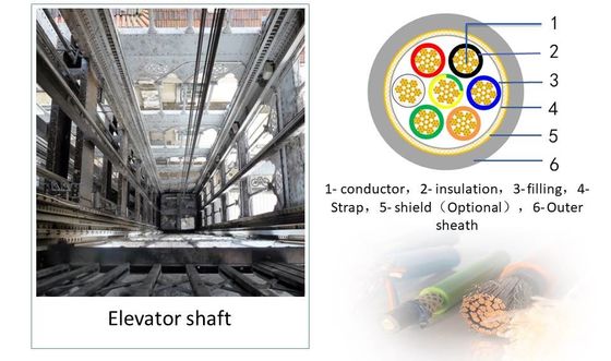
The wiring inside the elevator shaft with a rated voltage of 300V-the control signal cable is composed of copper conductor, insulation, filling, tape, shielding and outer sheath. The cable has the characteristics of high flexibility, high temperature resistance, oil resistance, flame retardancy, etc. At the same time, all materials of the cable comply with the latest environmental protection standards of RoHS&Reach.
Mainly used for fixed installation of signal transmission cables in elevator shafts.
Scope of application | Rated voltage | Recommended specifications | Recommended number of cores |
Control cabinet → hoistway switch wiring | |||
Safety circuit switch hoistway cable | 300V | 26AWG-14AWG | 7+1 |
Upper forced switch, lower forced switch, upper limit switch, lower limit switch, ladder lock switch, fire return switch | 300V | 26AWG-14AWG | 2+1 |
Door lock trunk cable and door lock branch cable in hoistway | 300V | 26AWG-14AWG | 2+1 |
Control cabinet → hoistway floor display wiring | |||
Floor display main line cable, floor display branch cable | 300V | 26AWG-14AWG | Number of layers +N+PE |
Note: The number of layers is 7 and above |
1- conductor,2- insulation,3- filling,4- Strap,5- shield(Optional),6- Outer sheath
Printing:E258652 AWM STYLE 2517 ***AWG 105℃ 300V VW-1— c AWM I/II A/B 105℃ 300V FT1 -LF- HWATEK
Conductor : Solid or Stranded
Insulation: Special mixed PVC
Shield or Braid: optional
Jacket: Special mixed PVC
RoHS,REACH Compliant,
Rated voltage:300V
Rated Temperature:-40℃-105℃
Flame: VW-1, FT1, FT2
Oil resistance: 60 ℃ or 80 ℃ Oil
Voltage withstand test:AC 2.0kV/1min
Number of cores*Specifications | Conductor structure | Conductor outer diameter | Average insulation thickness | Insulation outer diameter | Average thickness of sheath | Finished outer diameter | Cable net weight | Maximum conductor DC resistance (20℃) |
(mm) | (mm) | (mm) | (mm) | (mm) | kg/km | Ω/km | ||
2C*26AWG | 7/0.16 | 0.48 | 0.30 | 1.2±0.05 | 0.76 | 4.3±0.20 | 19.2 | 150 |
2C*24AWG | 7/0.20 | 0.60 | 0.30 | 1.3±0.05 | 0.76 | 4.5±0.20 | 21.9 | 94.2 |
2C*22AWG | 7/0.254 | 0.76 | 0.30 | 1.5±0.05 | 0.76 | 4.9±0.20 | 27.0 | 59.4 |
2C*20AWG | 7/0.32 | 0.96 | 0.30 | 1.7±0.10 | 0.76 | 5.3±0.20 | 33.7 | 36.7 |
2C*18AWG | 16/0.254 | 1.15 | 0.30 | 1.9±0.10 | 0.76 | 5.7±0.20 | 41.2 | 23.0 |
2C*16AWG | 26/0.254 | 1.49 | 0.30 | 2.2±0.10 | 0.76 | 6.4±0.30 | 55.2 | 14.6 |
2C*14AWG | 41/0.254 | 1.87 | 0.30 | 2.6±0.10 | 0.76 | 7.2±0.30 | 75.7 | 8.96 |
2C*18AWG+16AWG | 16/0.254 | 1.15 | 0.30 | 1.9±0.10 | 0.76 | 6.2±0.20 | 57.4 | 23.0 |
26/0.254 | 1.49 | 0.30 | 2.2±0.10 | 14.6 | ||||
2C*18AWG+14AWG | 16/0.254 | 1.15 | 0.30 | 1.9±0.10 | 0.76 | 6.6±0.30 | 66.7 | 23.0 |
41/0.254 | 1.87 | 0.30 | 2.6±0.10 | 8.96 | ||||
3C*26AWG | 7/0.16 | 0.48 | 0.30 | 1.2±0.05 | 0.76 | 4.5±0.20 | 22.0 | 150 |
3C*24AWG | 7/0.20 | 0.60 | 0.30 | 1.3±0.05 | 0.76 | 4.7±0.20 | 25.8 | 94.2 |
3C*22AWG | 7/0.254 | 0.76 | 0.30 | 1.5±0.05 | 0.76 | 5.1±0.20 | 32.0 | 59.4 |
3C*20AWG | 7/0.32 | 0.96 | 0.30 | 1.7±0.10 | 0.76 | 5.6±0.20 | 41.4 | 36.7 |
3C*18AWG | 16/0.254 | 1.15 | 0.30 | 1.9±0.10 | 0.76 | 6±0.20 | 51.4 | 23.0 |
3C*16AWG | 26/0.254 | 1.49 | 0.30 | 2.2±0.10 | 0.76 | 6.8±0.30 | 71.0 | 14.6 |
3C*14AWG | 41/0.254 | 1.87 | 0.30 | 2.6±0.10 | 0.76 | 7.6±0.30 | 98.2 | 8.96 |
Number of cores*Specifications | Conductor structure | Conductor outer diameter | Average insulation thickness | Insulation outer diameter | Average thickness of sheath | Finished outer diameter | Cable net weight | Maximum conductor DC resistance (20℃) |
(mm) | (mm) | (mm) | (mm) | (mm) | kg/km | Ω/km | ||
3C*18AWG+16AWG | 16/0.254 | 1.15 | 0.30 | 1.9±0.10 | 0.76 | 6.8±0.30 | 69.7 | 23.0 |
26/0.254 | 1.49 | 0.30 | 2.2±0.10 | 14.6 | ||||
3C*18AWG+14AWG | 16/0.254 | 1.15 | 0.30 | 1.9±0.10 | 0.76 | 7±0.30 | 78.1 | 23.0 |
41/0.254 | 1.87 | 0.30 | 2.6±0.10 | 8.96 | ||||
4C*26AWG | 7/0.16 | 0.48 | 0.30 | 1.2±0.05 | 0.76 | 4.8±0.20 | 25.9 | 150 |
4C*24AWG | 7/0.20 | 0.60 | 0.30 | 1.3±0.05 | 0.76 | 5±0.20 | 30.4 | 94.2 |
4C*22AWG | 7/0.254 | 0.76 | 0.30 | 1.5±0.05 | 0.76 | 5.5±0.20 | 38.7 | 59.4 |
4C*20AWG | 7/0.32 | 0.96 | 0.30 | 1.7±0.10 | 0.76 | 6±0.20 | 50.2 | 36.7 |
4C*18AWG | 16/0.254 | 1.15 | 0.30 | 1.9±0.10 | 0.76 | 6.6±0.30 | 63.4 | 23.0 |
4C*16AWG | 26/0.254 | 1.49 | 0.30 | 2.2±0.10 | 0.76 | 7.3±0.30 | 88.0 | 14.6 |
4C*14AWG | 41/0.254 | 1.87 | 0.30 | 2.6±0.10 | 0.76 | 8.3±0.30 | 124.3 | 8.96 |
5C*26AWG | 7/0.16 | 0.48 | 0.30 | 1.2±0.05 | 0.76 | 5.1±0.20 | 29.6 | 150 |
5C*24AWG | 7/0.20 | 0.60 | 0.30 | 1.3±0.05 | 0.76 | 5.4±0.20 | 35.7 | 94.2 |
5C*22AWG | 7/0.254 | 0.76 | 0.30 | 1.5±0.05 | 0.76 | 6±0.20 | 46.3 | 59.4 |
5C*20AWG | 7/0.32 | 0.96 | 0.30 | 1.7±0.10 | 0.76 | 6.6±0.30 | 59.9 | 36.7 |
5C*18AWG | 16/0.254 | 1.15 | 0.30 | 1.9±0.10 | 0.76 | 7.1±0.30 | 75.6 | 23.0 |
5C*16AWG | 26/0.254 | 1.49 | 0.30 | 2.2±0.10 | 0.76 | 7.9±0.30 | 106.0 | 14.6 |
5C*14AWG | 41/0.254 | 1.87 | 0.30 | 2.6±0.10 | 0.76 | 9±0.30 | 150.8 | 8.96 |
Number of cores*Specifications | Conductor structure | Conductor outer diameter | Average insulation thickness | Insulation outer diameter | Average thickness of sheath | Finished outer diameter | Cable net weight | Maximum conductor DC resistance (20℃) |
(mm) | (mm) | (mm) | (mm) | (mm) | kg/km | Ω/km | ||
5C*18AWG+16AWG | 16/0.254 | 1.15 | 0.30 | 1.9±0.10 | 0.76 | 7.9±0.30 | 95.7 | 23.0 |
26/0.254 | 1.49 | 0.30 | 2.2±0.10 | 14.6 | ||||
5C*18AWG+14AWG | 16/0.254 | 1.15 | 0.30 | 1.9±0.10 | 0.76 | 8.1±0.30 | 104.3 | 23.0 |
41/0.254 | 1.87 | 0.30 | 2.6±0.10 | 8.96 | ||||
6C*26AWG | 7/0.16 | 0.48 | 0.30 | 1.2±0.05 | 0.76 | 5.5±0.20 | 34.4 | 150 |
6C*24AWG | 7/0.20 | 0.60 | 0.30 | 1.3±0.05 | 0.76 | 5.8±0.20 | 41.3 | 94.2 |
6C*22AWG | 7/0.254 | 0.76 | 0.30 | 1.5±0.05 | 0.76 | 6.5±0.30 | 53.2 | 59.4 |
6C*20AWG | 7/0.32 | 0.96 | 0.30 | 1.7±0.10 | 0.76 | 7.1±0.30 | 70.0 | 36.7 |
6C*18AWG | 16/0.254 | 1.15 | 0.30 | 1.9±0.10 | 0.76 | 7.7±0.30 | 89.2 | 23.0 |
6C*16AWG | 26/0.254 | 1.49 | 0.30 | 2.2±0.10 | 0.76 | 8.6±0.30 | 125.7 | 14.6 |
6C*14AWG | 41/0.254 | 1.87 | 0.30 | 2.6±0.10 | 0.76 | 9.9±0.40 | 179.0 | 8.96 |
6C*18AWG+16AWG | 16/0.254 | 1.15 | 0.30 | 1.9±0.10 | 0.76 | 8±0.30 | 104.3 | 23.0 |
26/0.254 | 1.49 | 0.30 | 2.2±0.10 | 14.6 | ||||
6C*18AWG+14AWG | 16/0.254 | 1.15 | 0.30 | 1.9±0.10 | 0.76 | 8.4±0.30 | 115.3 | 23.0 |
41/0.254 | 1.87 | 0.30 | 2.6±0.10 | 8.96 | ||||
7C*18AWG+16AWG | 16/0.254 | 1.15 | 0.30 | 1.9±0.10 | 0.76 | 8.3±0.30 | 115.4 | 23.0 |
26/0.254 | 1.49 | 0.30 | 2.2±0.10 | 14.6 | ||||
7C*18AWG+14AWG | 16/0.254 | 1.15 | 0.30 | 1.9±0.10 | 0.76 | 8.4±0.30 | 123.0 | 23.0 |
41/0.254 | 1.87 | 0.30 | 2.6±0.10 | 8.96 | ||||
8C*18AWG+2C*16AWG | 16/0.254 | 1.15 | 0.30 | 1.9±0.10 | 0.76 | 10.3±0.40 | 157.6 | 23.0 |
26/0.254 | 1.49 | 0.30 | 2.2±0.10 | 14.6 | ||||
12C*18AWG+2C*16AWG | 16/0.254 | 1.15 | 0.30 | 1.9±0.10 | 0.76 | 10.9±0.40 | 196.2 | 23.0 |
26/0.254 | 1.49 | 0.30 | 2.2±0.10 | 14.6 |
The above products are non-shielded standard models, and can also be customized according to customer requirements or actual usage.
UL, CUL, CE
Contact Person: Jimmy Wang
Tel: 17715039722